

Fusion Science & Related Technologies
Fusion Science & Related Technologies
To realise thermonuclear fusion, a vast majority areas of different technologies have to work in tandem: High current electromagnets, advanced material technologies, robotic technologies, cryogenic technologies, beam technologies, Radio-Frequency wave technologies etc. Also these technologes have to work in a very hostile environments which includes nuclear radiations. Continuous progress related to these technologies are being made with relevant science and engineering.
Magnet Technologies
Magnet technology is one of the important requirements for the magnetically confined tokamak plasmas, as it takes the major share of the fusion machine. For steady state operations superconducting magnets are preferred over copper magnets. Starting from Cryogenic temperature based superconducting magnets, efforts are being carried out to apply high temperature superconducting magnets.
Recent developments:
Fabrication and testing of compact HTS solenoid coil: High temperature superconductors (HTS) are promising candi-dates for next generation high field compact magnets, since they do not require cryogenic cooling at 4 K. Coil winding, inter-pancake and terminal joints are challenging technologies required for the fabrication of HTS tape based high-field magnets. As a first step, IPR has fabricated a small bore (~50 mm) double pancake, liquid nitrogen bath-cooled, HTS solenoid coil with 24 turns and a height of 21 mm. This has produced a pulsed magnetic field of 1.1 Tesla with a current pulse of duration 0.72 millisec, and a DC magnetic field of 0.06 Tesla at 110 A current. Figure A.4.1.1 shows the HTS coil assembly used to measured magnetic fields. The next step will be to develop higher-field and larger bore HTS coils for practical applications these activities are covered in a new DPR titled “Fusion Technologies” that has been cleared by PAC and is awaiting DAE sanction.
 Figure A.4.1.1 HTS coil assembly
|  Figure A.4.1.2 Hybrid Joint integrated with the test insert
|
Indigenous Development of Hybrid Nb3Sn and NbTi CICC joint: Systems with superconducting magnets often require joints between different kinds of superconducting materials. For the first time in India, IPR has developed a hybrid over-lap joint of length 120 mm, for connecting Nb3Sn and NbTi Cable-in-Conduit-Conductor (CICC). This is a thermally stable joint operating at 4.5 K and currents upto 10 kA. This joint is of practical importance because it can be integrated in the limited space available near Nb3Sn CICC-based super-conducting magnets
Integrated Magnet Test Facility:An integrated magnet test facility (MTF) has been installed & commissioned at IPR. This facility is meant for testing high temperature (80-4.5 Kelvin) as well as low temperature (~4.5 Kelvin) supercon-ducting magnets for fusion & other applications. It consists of a large Cryostat weighing 21 Tons and having a volume of 83 m3, along with a liquid nitrogen thermal shield. It is capable of housing superconducting magnets with a maxi-mum size of 5 m height and 4 m diameter. The vacuum and cool down performance of the thermal shields of this cryostat have been found to be satisfactory.
 Figure A.4.1.3. (a) Integrated Magnet Test Facility (MTF)
|  (b)Thermal shields of bottom part of cryostat
of the MTF
|
Here the basic fundamentals of Nuclear Fusion will be added soon...
Integrated flow distribution and control system of SST-1 Cryogenics (IFDCS)
Introduction: Integrated flow distribution and control system of SST-1 Cryogenic facility is used
to distribute and control flow of cold power of helium produced in Helium Refrigerator/Liquefier (HRL)
to Superconducting magnet systems (SCMS) of SST-1 tokamak as per the requirement. It consists of a vacuum chamber which houses 80K thermal shield, Supercritical helium hydraulics network,electro-pneumatic valves, sensors and flow meters. The main objective of this system is to facilitate hydraulic balance of helium in the SCMS. During the initial cool down campaigns of SST-1 tokamak, cool down of PF coils to superconducting temperature was not achieved due to hydraulic imbalance of helium among the PF coils. To overcome this drawback grouping of PF coils inside SST-1 machine was carried out which further demands up gradation in the Integrated flow distribution and control system. Implementation of same has been done successfully.
 Inside of IFDCS
|  External of IFDCS
|
Recent Developments: Up gradation of Integrated flow distribution and control system of SST-1 Cryogenic facility has been implemented to facilitate the flow and control of Supercritical helium in the modified groups of PF coils. (PF-3 and PF-5)
Up gradation involves
1) Modification of Supercritical helium hydraulics network inside IFDCS
2) Introducing additional hydraulics network and electro-pneumatic valves for distribution & control of Supercritical helium in the modified groups of PF coils
3) Introducing additional flow meters, sensors etc..
4) Making of new nozzles on the Vacuum chamber

Achievements
1) After up gradation of IFDCS helium leak tightness of all the hydraulics inside the IFDCS as well as global helium leak tightness of IFDCS has been carried out and found satisfactory.
2) IFDCS Integrated with multi channel super insulated helium transfer line successfully.
3) Because of dedicated hydraulics and valve, control of flow in PF-coils was possible and also able to cool PF3 coils to superconducting temperature which was not achieved with single supply and return valve for all PF coils.
4) It was in operation during the last 10 SST-1 campaigns and performed well.
Indigenous development of cryo compatible flexible vacuum jacketed cryo line
Introduction
The flexible line is used for transfer the cryogenic liquid at low temperature. The basic structure of the transfer line consists of two concentric tubes, inner process tube wrapped with a multi-layer super-insulating material fixed by G-10 insulation material spacers inside the outer jacketed tube having a vacuum of order 10-2 mbar.
Technical specifications :
Helium leak tightness (LN2 flow condition) : 1.3 x 10⁻⁹ mbar-l/s
Temperature and Pressure : 300 to 77 K, 0-3 bar (a)
Vacuum retention : <1x10⁻² mbar in 24 h
Pressure drop at 78.6 K, 1.07 bar (a) : 4.15 mbar
Mass flow rate : 19.34 g/s
Transfer with minimal loss : 1.0 – 1.5 W/m
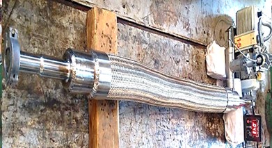 Developed cryo transfer line Developed cryo transfer line | 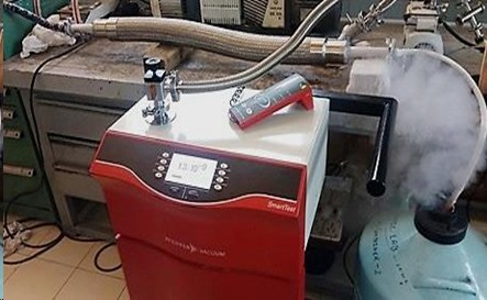 Performance test at 77 K
|
Recent Developments
Designed and in-house development of vacuum jacketed cryogenic corrugated flexible line
Helium leak test of inner and outer corrugated pipes before assembly
Design and fabrication of low thermal conductive GFRP spacer
Raw material chemical and mechanical test
Hydro and pneumatic test at Factory inspection
In-house assembly, super-insulation application and welding of cryo flexible line
NDT (Non destructive test ) of weld joints
Bending radius test
Performance tests at 300 K and 77 K in IP
Achievements
The Cryo flexible transfer line in-house developed and performed as per the needs and application requirement.
The dominated heat load of residual gas conduction could be reduced drastically by enhancing the vacuum level > 10 mbar.
The heat leaks, helium leak tightness of < 10-8 mbar l/s , nominal pressure drop and other achieved performance parameters of in-house developed line could be comparable with imported foreign make lines.
In-house developed Line costs significantly less than that from outside Industries. The item is not commercially available in local Indian market.
It can be used for Transfer of cryogenic fluids such as LHe, LN2 for daily common laboratory use, Connections in hydraulics for joining and Helium leak testing at cryogenic temperature and Industrial uses in connection for filling of cryogens to magnets of MRI, LN2 Food Freezers.
Advancement task for different sizes, bigger length and performance enhancement of the line is continues.
In-house development of Electrical Insulation Breaks for 4.2 K and 77 K Applications
Introduction
Electrical insulation breaks (IB) for is a very crucial component of superconducting magnet fusion machines, main function of such insulation break is to supply Liquid helium/Supercritical helium to super-conducting coils and to isolate the magnet electrically from ground potential when quench occurs in such magnets.
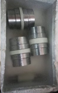
Salient Features of the In-house Developed Component
 Sizes: 8 mm, ½” NB Size of metal conductorS-2 Glass fibre insulation, Stainless steel (SS 316 L) and Cryogenic resin systemWorking condition (inside): 4 bar supercritical helium flow at 4.5 KHelium leak rate better than 10-8 mbar l/s @ 4.5 K with Super-critical helium flow to vacuum compatibility (outside) : 10-5 m barPressure withstand : 40 Bar (a)Electrical Isolation : > 5 kV DC (withstand up to 30 kV AC)Helium leak rate <1.0x10⁻⁸ mbar-l/s under mechanical loading condition at 300 K, 77 K and 4.2 K (i) 2000 N Tensile load (ii) 100 N-m Bending and (iii) 100 N-m Torsion load
  |  |
Recent Developments
Selection of compatible insulation material (S-glass boron free)as per the application needs Raw material test of Insulation materialMechanical and Electrical performance tests as Tensile, Compressive, Interlaminar Shear, Impact, Dielectric strength, Surface resistivity Material heat deflection, Glass transition temperature Tg on insulation material.Development of indigenous epoxy resin system for cryogenic application Filament winding process optimized and established for fabrication of Physical, thermal and mechanical performance test at 300 K and 77 K of epoxy resin system Helium leak rate at 300 K and 77 K ≤ 10-8 mbar l/s (dissimilar material joints of glass-fiber and S S316L metal )Thermal cycle test at LN2 temp.Scanning electron microscopic (SEM) test of dissimilar material jointPerformance test of complete fabricated electrical insulation breaks in batch wiseValidation and performance of the component in the system/SST-1 machineInsulation material compatible and experimentally validated experimentally validated up to 1021 n/m2 neutron fluence and 1 MGy radiation doseAchievements
Developed electrical insulation breaks have been used and validated in superconducting coils, 10 kA current lead and current feeder system in cold return circuit of SST-1 (Steady State Superconducting Tokamak) machine.It can be used for future indigenous superconducting magnet fusion machines, electrical isolation/insulation and for low temperature experiments purposes.In-house developed component is very much cost effective compared (10 to 15 times less) to outside Industries not commercially available item.In-house Development of Vacuum Barrier for Superconducting Feeder System
Introduction
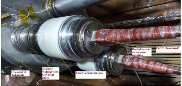
The vacuum barrier (VB) is a dissimilar materials joint which bifurcate the vacuum between the SST-1 machine cryostat and current feeder system and provides the electrical isolation upto 5 kV DC voltage during quenching of SC (Super Conducting) magnets.
The complete vacuum barrier consists of SS 316L stubs which are separated by glass fibre tubes of G-10 CR bonded with cryogenic grade epoxy.
Wet filament winding process optimized for manual and Auto method in 4-axis winding machine. Passing the helium leak tightness and thermal shock test at 300 K and 77 K QA/QC followed in each stage of fabrication as joint bonding, wet filament winding.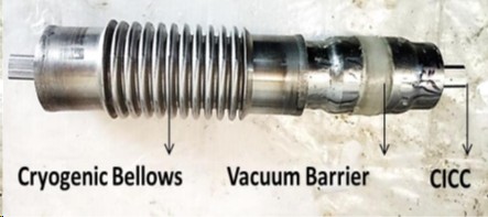 | 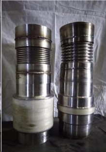 In house developed vacuum barrier
|  Thermal cycle test at 77 K
|
Recent Developments
Selection of compatible insulation material (S-glass boron free)as per the application needs Raw material test of Insulation material Mechanical and Electrical performance tests as Tensile, Compressive, Interlaminar Shear, Impact, Dielectric strength, Surface resistivity Material heat deflection, Glass transition temperature Tg
on insulation material.
Development of indigenous epoxy resin system for cryogenic application Filament winding process optimized and established for fabrication of Physical, thermal and mechanical performance test at 300 K and 77 K of epoxy resin systemHelium leak rate at 300 K and 77 K ≤ 10-8 mbar l/s (dissimilar material joints of glass-fiber and S S316 L metal )Thermal cycle test at LN2 temp.Scanning electron microscopic (SEM) test of dissimilar material jointPerformance test of complete fabricated electrical insulation breaks in batch wiseValidation and performance of the component in the current feeder system of SST-1 machineInsulation material compatible and experimentally validated experimentally validated up to 1021 n/m2 neutron fluence and 1 MGy radiation doseAchievements
In house developed component costs significantly less than that from imported available and mitigated the brittle failure aspects at cryogenic temperature
Electrical Dc voltage test from 100 V to 5 kV range at 5 kV insulation resistance : ≥ 100 GΩLeakage current : 5 x 10⁻⁸ Amp.High impulse voltage test: 40.2 kV/sIR measurement test at 10 kV: 40.3 nA , 20 mm gap in metal conductors In-house Development of High Neutron Resisted Insulation Material For Superconducting Magnets Fusion Machines and 77 K, 4.2 K Applications
Introduction
In Fusion Reactor, high demand of insulation materials to withstand neutron resistance after irradiation which degrades the properties of materials and components which overall effect the performance of Fusion Reactor.The irradiation effect of neutron degrades the properties of insulation materials and components which overall effect the performance of fusion reactor. Experimental results reported that under the high neutron fluence (1014 to 1022 n/m2) on insulation materials degrades the mechanical performance from especially 0-30% as tensile, interlaminar shear strength. Application of insulation materials in electrical insulation breaks, structural and support structure materials for electrical isolation in superconducting fusion Tokamak.Developed GFRP (Glass fiber reinforced plastic) composites Insulation samples irradiated in sodium cooled PU carbide fuel Fission Reactor at IGCAR, Kalpakkam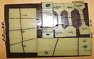 Developed GFRP insulation material for irradiation
| 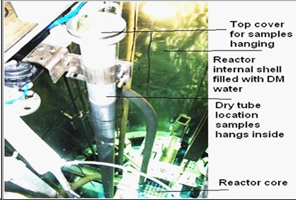 Material Irradiation in KAMINI Reactor, IGCAR, Kalpakkam
|
Recent Developments
Insulation material GFRP composites consists of S-2 fibre glass (Boron free) and In house developed liquid modified Bisphenol epoxy resin irradiated in FBTR (Fast Breeder Test reactor) at IGCAR, KalpakkamRadiation dose (Gamma and Neutron ) measurement done on irradiated samplesSimulation result by Neutron code MCNP (Monte Carlo N- Particle) and EASY (European Activation Systems uses Fish Pacts)Insulation sample irradiated at Reactor full power 32 MWt at neutron flux 2.10 x 10¹⁰ n/cm2 .s location for 60 daysMechanical and Electrical performance done on un irradiated and irradiated insulation sample at ERDA, Vadodara Achievements
Developed insulation material irradiated has been experimentally validated up to 1021 n/m2 neutron fluence and 1 MGy radiation dose.From the test results no significant degradation ( < 2%) is observed in tensile, shear and breakdown strength properties of the insulation material. The insulation material passed the acceptable limit of radiation damage dose ( ≥ 1020 n/m2 )Acceptable radiation tolerance limit of GFRP insulation material of neutron fluence of 1020 to 1022 n/m2Gamma radiation dose found in acceptable sample on samples 5.0 µ-Sv/hr in all samples contact (Measured at IPR, Gandhinagar, Acceptable limit Annual safe dose limit of Radiation for Public: 1mSv/year)
In-house development, designed and Fabrication of Filament Winding Machine
Introduction
Filament winding, in which the fibres are passed through a resin bath and wound onto a rotating mandrel. This type of low-cost system is generally used in commercial applications with polyester and epoxy resins.To make dissimilar material joints and filament winding job to form a round shape items.The epoxy resin field is affected by several parameters: resin viscosity, the squeeze rollers, winding tensioner, the number of layers etc.Salient features of developed machine :
Wet type filament winding, Controlled adjustable RPM: upto 30 RPM by DC motor and gear box assembly mechanismEasy movable Cylindrical/ Round job span: 10-100 mm dia and winding length: 0-300 mm, Fibre speed: < 6 mm/sec Manufactured by Local Indian Industry Machine cost significantly less (5 to 6 times) than of similar capacity machine.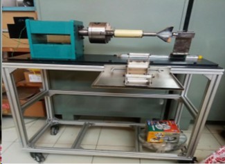 In house developed filament winding machine
| 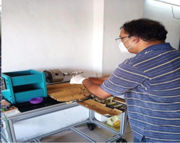 Manual Filament winding job on developed machine
|
Recent Developments
Development and optimization of filament winding process for dissimilar materials joints of IB and VB.Design of glass fibre speed control assembly and epoxy resin roller set up.Winding parameters established for fabrication of cryo components, torque, fibre speed, winding angle etc.
Design of fibre roving holding set up, 2 numbers of fibre roving can be used for filament winding process.In house development of epoxy resin system for cryogenic applicationGlass fibre composites sample (round shape ) fabricated and optimization of ration of glass fibre and epoxy resin in the final component.
Measurement of glass fibre and epoxy resin density and void fraction in winded product.Fabrication of batch wise IB and VB in the developed filament winding machine.Mechanical and Electrical Performance tests passed of winded componentsAchievements
In housed developed filament winding machine is acceptable for cryogenic components as IB and VB .The winded comments on machine passed the acceptable helium leak tightness criteria.Any cylindrical/Round job can be performed on this machine upto 100 mm dia and 300 mm length.Better surface finished achieved in components. Winded components passed the acceptable mechanical strength and electrical isolation criteria.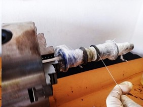 Filament winding of IB component
| 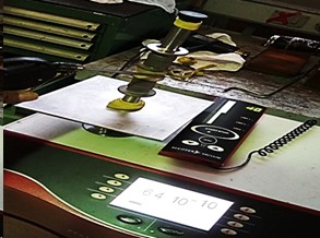 Helium leak tightness test of winded component
|
High Temperature Technologies Division (HTTD) is involved in research and development in the following areas:
Engineering Design, Analysis & Simulations related to Plasma Facing Components (PFCs) for magnetic plasma confinement/fusion devices such as TokamaksDevelopment of material s & technologies relevant to PFCs including Plasma Facing Materials, Material joining/coating techniques, Design & Fabrication of PFCs, Inspection, Testing and Qualification of PFCsHigh Heat Flux Test Facility (HHFTF), GLEEBLE3800, Vacuum Brazing Furnace, Magnetron Sputter-Coating System, Ultrasonic & Infra-Red Testing & Calibration Equipment, Laser-Flash Thermal Diffusivity System and Computational Resources (Software & Hardware ) are some of the major facilities/equipment available with HTTD that are useful in the R&D work related to PFCsPlasma Facing Components (PFCs) of Tokamaks experience intense particle, thermal, electromagnetic and neutronic loads due to their close vicinity surrounding hot and dense plasma in a Tokamak device. PFCs are typically divided in two categories viz. Divertor and Firstwall, depending on their positioning and functionalities with respect to core plasma confined using magnetic flux surfaces of a tokamak. Firstwall PFCs receive low thermal loads but they covers majority of the area surrounding core plasma region. Divertor PFCs covers relatively smaller region but they receive intense loads. High energy plasma particles escaping from the core plasma region are diverted onto Divertor using specially shaped magnetic flux surfaces surrounding core plasma region so that the Plasma-Wall interactions can occur in a specific region away from the main plasma core region that minimizes the core plasma from getting contaminated due to impurities from surrounding walls. A typical Plasma Facing Component is made of plasma facing (refractory) materials such as Tungsten, Graphite or Carbon Fiber Composites that are mounted on actively cooled using metallic substrates made of Copper or Stainless Steel.
Recent developments:
Some of the ongoing activities/ developments at HTTD are as follows:
Critical Heat Flux (CHF) studies on PFCs with One-Sided Heating conditions using HHFTF.Target Handling System Development and Integration with HHFTF for testing Helium Cooled PFCs.Brazing technique development to fabricate PFCs in Mono-block and Macro-brush types.Development of Finger type Helium cooled Plasma facing components.Setup of Liquid Metal Processing loop for producing Tin-Lithium (Sn-Li) alloys to be used as plasma facing material.Shear Punch testing of Tungsten material at elevated temperatures up to 1000 C.
Clockwise from top: The HHFTF system showing (A) the electron beam chamber and (B) the water-cooling system. (C) Closeup of the electron beam gun of the system
Recent Publications
1) Demonstration of heat flux uniformity by infrared imaging in high heat flux test facility at IPR, Kedar Bhope, Sunil Belsare, Samir Khirwadkar,vinay Menon, Mayur Mehta, Rajamannar Swamy,nikunj Patel, Tushar Patel, Sudhir Tripathi, K. P. Singh, Prakash Mokariya, IPR/RR-1269/2021 , Apr-21.
2) Sonic velocity measurement in molten pb-li(16) at high temperature, S. Sahu, K. Bhope, A. Prajapati, M. Mehta, H. Tailor, R. Bhattacharyay, S. S. Khirwadkar, IPR/RR-1321/2021 , Aug-21
3) Temperature response of laser heated emissive probe materials under vacuum and free atmospheric conditions, Abha Kanik, Arun Sarma, Joydeep Ghosh, Amarnath Elumalai, Shwetang Pandya, Kedar Bhope,Ranjana Manchanda, Laser Physics, Volume 31, Issue 1, id.016002, 10 pp., Jan-21.
4) Validation of 2D DIC technique with Strain gauge for cantilever displacements, Kedar Bhope, Mayur Mehta, Sunil Belsare, Tushar Patel, Nikunj Patel, Samir Khirwadkar, IPR/TR-644/2021, Aug-21.
Fusion Blanket Technologies
High energy neutrons generated from the fusion reactor needs to be utilized for breeding tritium fuel as well as for utilizing the energy. The Blanket acts like heat exchanger as well as to generate tritium fuel from lithium. This development work is being currently undertaken at IPR.
Recent developments:
Thermal-hydraulics and structural analyses of LLCB TBM set: Indian Lead-Lithium cooled Ceramic Breeder (LLCB) Test Blanket Module (TBM) is one of the tritium breeding Fusion blanket concepts. First wall (FW) is a plasma facing component of the TBM designed to withstand high heat flux from plasma. FW is cooled by high pressure, high temperature helium gas flowing through coolant channels. The detailed thermal–hydraulics of FW has been performed based on the heat flux and neutronic heat generation. using ANSYS CFX. The distribution of flow in different flow circuits of FW from manifolds has been performed and the flow distribution is found to be uniform in all the circuits. Thermal-hydraulic analysis of helium flow inside the FW channels has been done and then the manifolds to estimate temperature, pressure drop and heat transfer coefficient have been documented. TBM shield is located behind TBM to provide shielding from high energy neutrons to magnets and other components behind the TBM set. Water flows in parallel channels inside TBM Shield, provides the function of neutron moderator as well as coolant to remove heat deposited by the neutrons in the structure. Flow rate in parallel channels of shield has been regulated using orifice of different diameter. CFD Flow analysis inside shield has been performed to validate the distribu-tion of flow inside the parallel channels. Based on velocities obtained, the heat transfer coefficients have been evaluated and thermal analysis of TBM shield has been performed considering thermal load from neutronic heat generation. The results obtained from thermal–hydraulic analysis of FW, manifolds and TBM shield have been used for thermo-structural analysis of LLCB TBM set based on load combinations as per ITER load specifications. RCC-MR 2007 code has been used for the structural assessment and prevention of ptype and s-type damages. The temperature and stresses are found to be within the acceptable limits and safety margins with some proposed modifications.
Performance Assessment of the Helium Cooled First Wall Mock-Up in HELOKA Facility: The Lead-Lithium Ceramic Breeder (LLCB) Test Blanket Module (TBM) being developed by India for testing in ITER adopts various well developed design engineering and manufacturing technologies. The First Wall (FW), which is directly exposed to the incident heat flux, is designed for high pressure helium flow, high operating temperature (up to 100 bar and 550 °C) and considerable thermal stress and electromagnetic disruption loads. In order to check the thermal performance of the FW and ensure its structural integrity, a mock-up of the FW fabricated in India was tested in HELOKA test facility at KIT, Germany. Both normal and accidental operating conditions were investigated under ITER-like surface heat fluxes. Based on these results the thermal performance of the FW were validated.
3D Modelling of Loop Layout, Pipe Stress Analysis and Structural Responses of High-Pressure High-Temperature Experimental Helium Cooling Loop (EHCL): An Experimental Helium Cooling Loop (EHCL) is being developed as a part of R&D activities in fusion blanket technologies. This system is designed to test various nuclear fusion blanket mock-ups. The primary loop is designed to remove 75 kW heat load on the Test Section Module (TSM). This system is a high-pressure high-temperature loop which produces significant deflections and thermal expansions in the piping network, which leads to the reaction forces and moments. During the earthquake, an additional high acceleration acts (in all directions) on the piping system which again enhances the pipe deflections. EHCL equipment arrangement, loop layout, methodology and results of pipe stress analysis have been studied. EHCL equipment are connected through DN 50 schedule 80 major pipes and associated valves. The high temperature piping network is analyzed for sustained and occasional load responses to ensure the integrity of the system. The process piping code ASME B31.3 is referred for pipe stress analysis. The calculated stresses are in acceptable limit. The least available stress margin is ~29% and the corresponding displacements are of 9.8 mm, 19.72 mm and 21.76 mm in x, y and z directions respectively are observed in the heater outlet to TSM inlet line. The obtained results of reaction forces and moment forces would be utilized as an input for the selection of pipe. supports. The results of pipe stress analysis would be used in further loop optimization.
Automation and Interlock System Design for BP-Li Liq-uid-Metal Purification Experimental Facility: In nuclear fusion domain, eutectic lead-lithium (Pb-Li) is of critical importance as a tritium breeder, neutron multiplier as well as a high-temperature coolant for nuclear power plants. To achieve intended plant efficiency through operation of such high-temperature fluid systems, it is necessary to control composition characteristics of operating fluid. In contrast, at elevated temperatures and higher velocities lying within op-erational region of interest, Pb-Li plays role of an active corrodent for structural materials, exhibiting selective leaching towards certain elements like Ni, Cr, Mn etc. Such elemental impurities alongwith oxides tend to precipitate in cooler sections of the system, thereby restricting flow of coolant resulting in overall performance degradation. To maintain the pu-rity of Pb-Li, online removal of impurities is essential. In this regard, an online Pb-Li purification facility is under fabrication. Performance evaluation of this facility will be assessed over long duration operations at relevant process conditions. To operate the facility with minimum human-intervention and downtime, a PXI-express platform based data-acquisi-tion and control system is designed using LabVIEW environment for continuous monitoring and control of process pa-rameters. Investment protection for critical loop components is addressed using software based interlock modules. The details about the developed data-acquisition system, definitions for control and interlocks logics, alarm management, remote operation of loop components and salient integrated features for a user-convenient long-duration automated operation of the facility are documented. Detailed design and validated performances for cover gas pressure control system and timer-based latched configuration liquid-metal drain in-terlock are also studied.
Development of an Optimised Magnetic Field Source for Flowmeter Applications: Sensitivity of a magnetic flowmeter relies on many factors like magnetic field strength, gap between electrodes, material properties, magnet temperature etc. For a given measuring conditions, a strong magnetic field source can produce highest sensitivity for the flowmeter. An economic design of magnetic field source would be to produce the strongest magnetic field from a given amount of magnetic material. For this purpose, various magnet configurations are analyzed using FEM and the flowmeter sensitivity using such magnet configurations are compared. It is observed that magnets arranged in a Halbach fashion produce the highest sensitivity for the flowmeter using a given amount of magnetic material. The major challenge for the development of such a magnetic field source is its fabrication from its constituent magnets, combatting their huge attractive/repulsive forces (~2500 N for our case). Therefore, a specific mechanical tool has been designed for assembling the magnetic field source and a robust assembly technique has been devised using nu-merical computations. The designed magnetic field source produces a peak magnetic field of 0.78 T in the pole cross section of 50 mm × 50 mm.
A Neutronic Experiment to Support the Design of an Indian TBM Shield Module for ITER: A shield module is associated with an Indian Test Blanket Module (TBM) in ITER to limit the radiation doses in port inter-space areas. The shield module is made of stainless steel plates and water channels. It is identified as an important component for radiation protection because of its radiation exposure control functionality. The radiation protection classification leads to more assurance of the component design. In order to validate and verify the design of the shield module, a neutronic laboratory-scale experiment is designed and executed. The experiment is planned by considering the irradiation under a neutron source of 14 MeV and yields of 1010 n s−1 . The reference neutron spectrum of the ITER TBM shield module has been achieved through optimization of the neutron source spectrum by a combination of steel and lead materials. The neutron spectrum and flux are measured using a multiple foil activation technique and neutron dose-rate meter LB 6411 (He-3 proton recoil counter with polyethylene), respectively. The neutronic design simulation is assessed using MCNP5 and FENDL 2.1 crosssection data.
Flowmeter for high temperature conducting fluids
Flowmeters are being used in general to measure the amount of liquid being flown in a pipe. These are readily available commercially for low temperature applications. The task becomes challenging if there is high operational temperature and corrosive fluid involved. IPR has developed Magneto Hydro Dynamic (MHD) type flowmeters for high temperature applications, which have high precision and can work with corrosive/non-corrosive electrically conducting fluids. It works on the Faraday’s law of induction, wherein an emf is generated in a conducting fluid when it travels through a transverse magnetic field. The flowmeters are successfully tested at temperatures of 300 Degree C-350 Degree C, 3 bar, flowrates of ~ 100 ltr/m. It utilizes a magnet arrangement producing a magnetic field of ~ 0.8 T and provides a high sensitivity of 0.33 mV×min/ltr and can be continuously used in high operational temperatures. In order to calibrate such flowmeters, sophisticated calibration facility and numerical techniques have been developed and verified.


Electromagnetic pump for high temperature electrically conducting liquids
A pump is usually used to flow a liquid in a pipe. IPR has developed an electromagnetic pump for driving hot electrically conducting liquids at temperature 300 Degree C-350 Degree C. The pump consists of alternate arrangement of permanent magnets inside a magnet disc producing a peak magnetic field of ~ 0.5 T. When these magnet discs are rotated using a motor, a time varying magnetic field is produced which induces a current in the liquid, that produces Lorentz forces to drive the liquid in the pump. The pump can generate a pressure of 3 bar at a flowrate of 0.6 l/s for heavy liquid metals. Numerical simulation was performed in order to calculate the forces on magnet pieces such as to deduce a proper assembly sequence and mechanical tool to handle high attractive/repulsive forces among the magnets.

Diagnostics development/qualification for high temperature liquid metals
Various diagnostics tools like flowmeters, pressure sensors, level sensors etc. are being developed and/or being qualified for high temperature liquid metal applications. In this connection, several precision flowmeters have been designed, fabricated and calibrated at operational temperatures as high as 300 Degree C-350 Degree C [1]. These work on the Faraday’s law of induction, wherein an emf is generated in a conducting fluid when it travels through a transverse magnetic field. To calibrate such flowmeters sophisticated experimental facilities has been designed and fabricated using novel techniques. In addition, numerical techniques have been developed and verified to dry calibrate such flowmeters [2]. Specially designed flush face pressure transmitters have been qualified for accurate pressure measurement of high temperature liquid metals. These pressure transmitters have a thin membrane in contact with the fluid, behind which there is an intermediate liquid, which transfers the pressure seen by the membrane to the strain gauge to produce the signal. The pressure transmitter can measure a pressure up to 20 bar (g) with accuracy of ± 0.01 bar. Radar level sensors have been applied and verified to be compatible with high temperature liquid metal application. The radar level sensor sends a radio wave to the surface of the liquid and records the time for the wave to get reflected back from the surface. From the transit time data the level is being estimated in the sensor. The radar level sensor was found to provide good accuracy up to ~ 6 mm [3].

Publications:
[1] An Indian patent has been filed with patent no # 202121006697 dated 17th Feb 2021
[2] S. Sahu, A. Prajapati, et. al., “Development of an optimised magnetic field source for flowmeter applicaitos”, Flow Measurement and Instrumentation”, 66 (2019) 190-199
[3] A. Saraswat, S.Sahu et. al., “Development of diagnostics for high temperature high pressure liquid Pb-16 Li applications”, World Journal of Nuclear Science and Technology, 2017, 7, 292-308
Electromagnetic pump for heavy corrosive liquid metals
A pump is usually used to flow a liquid in a pipe. IPR has developed an electromagnetic pump for driving hot electrically conducting liquids at temperature 300 Degree C-350 Degree C. These are specifically recommended for corrosive high temperature liquids. The pump consists of alternate arrangement of magnets inside a magnet disc producing a peak magnetic field of ~ 0.5 T. When these magnet discs are rotated using a motor, a time varying magnetic field is produced which induces a current in the liquid, that produces Lorentz forces to drive the liquid in the pump. The pump can generate a pressure of 3 bar at a flowrate of 0.6 l/s for heavy liquid metals. Numerical simulation was performed in order to calculate the forces on magnet pieces such as to deduce a proper assembly sequence and mechanical tool to handle high attractive/repulsive forces among the magnets [1]. In addition, the mechanical force (Lorentz force) developed in the pump was computed numerically by solving the coupled Maxwell’s and Navier Stoke’s equations.


Publications:
[1] S. Sahu, R. Bhattacharyay et. al., “Preliminary design of a permanent magnet based electromagnetic pump for Pb-Li applications” IPR/2021-2022/TR-628
Advanced computer simulation of magnetohydrodynamic effects
Numerical simulations are being performed to study the mutual interaction between the liquid metal flow and the magnetic field. This has led us to design and develop flowmeters, electromagnetic pumps in addition to the study of the magnetohydrodynamics effects prominent in futuristic nuclear fusion reactors. Few examples are, (A) capturing of reduction in pressure developed in an ALIP (Annular Linear Induction Pump) due to the formation of reversed flow at the exit of the pump. (B) Numerical capture of Quasi-2-Dimension turbulence velocity profile showing eddies restricted near the walls for a liquid metal flow under transverse magnetic field and vertical heat flux against gravity. These type profile appears at certain flow parameters which don’t appear at other flow parameters depending upon the dominance of force among inertia, buoyancy and electromagnetic forces [1].


Publications
1] S. Sahu, K. Bhope et. al., “Sonic velocity measurement in molten Pb-Li(16) at high temperature”, IPR/2021-2022/RR-1321
[2] S. Sahu, R. Bhattacharyay et. al., “Preliminary design of a permanent magnet based electromagnetic pump for Pb-Li applications” IPR/2021-2022/TR-628
[3] An Indian patent has been filed with patent no # 202121006697 dated 17th Feb 2021
[4] S. Sahu, C.Courtessole et. al., “ Thermal convective studies in liquid metal flow inside a horizontal duct under the influence of transverse magnetic field”, Physics of Fluids, 32, 067107 (2020)
[5] S. Sahu, A. Prajapati, et. al., “Development of an optimised magnetic field source for flowmeter applicaitos”, Flow Measurement and Instrumentation”, 66 (2019) 190-199
[6] S. Sahu, R. Bhattacharyay, “ Validation of COMSOL code for analyzing liquid metal magnetohydrodynamic flow”, Fusion Engineering and Design, 127 (2018) 151-159
Design, development and testing of Cold Trap (CT) for Pb-16Li purification
Cold Trap (CT) is a purification unit that is used for the removal of impurities from liquid metals such as Lead Lithium Eutectic, Lead Bismuth, etc. CT works on the temperature solubility relationship of impurities dissolved in liquid metal. An experiment was carried out continuously for the duration of ~3500 hours at IPR to remove the dissolved impurities (such as Nickel and Iron) from the Lead Lithium eutectic using developed Cold Trap.
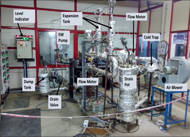
Birds eye view of Pb-16Li purification system at IPR
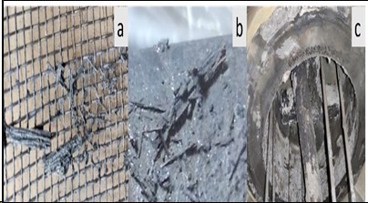
Deposition of corrosion impurities on the surface of a) wire mesh packing and b) outlet pipe, c) deposition of oxide impurities on interior walls of CT
Ref: A. Deoghar et.al, Entrapment of impurities inside a cold trap: a purification process for removal of corrosion impurities from molten Pb-16Li, 2021 Nucl. Fusion 61 116027
Indigenous Pb-16Li Production and its qualification
An in-house Lead Lithium Eutectic (Pb-16Li) production system has been developed at IPR for the production of Pb-16Li ingots. The system uses MHD stirring technique to mix the molten lead and molten lithium to produce Pb-16Li alloy. The capacity of the system is ~75kg per batch. The samples from the produced Pb-16Li ingots have been characterized through Differential Scanning Calorimetry (DSC) analysis to determine the melting point of the sample. The result of the analysis confirms the formation of Pb-16Li eutectic. The elemental analysis to determine the composition of Li in the Pb-16Li sample is under progress. The produced Pb-16Li ingots will be used in the various liquid metal experiments at IPR.
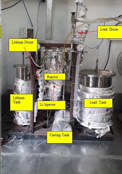
Pb-16Li production system at IPR
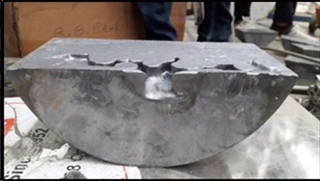
Produced Pb-16Li ingots
Recent Publications:
A. Deoghar et.al, Entrapment of impurities inside a cold trap: a purification process for removal of corrosion impurities from molten Pb-16Li, 2021 Nucl. Fusion 61 116027
Large Volume Cryoplant Systems
The future fusion based power stations are expected to have very large super-conducting magnets which would require very large cryogenic plants. This activity involves building modular cryogenic plants each of 1MW capacity.
Recent developments:
Indigenous helium compressor for cryoplant application: One of the major components in a cryoplant is a helium compressor, which is normally imported. As a significant step towards indigenisation, an industry-scale air compressor has been successfully converted to a helium compressor. This has been operated successfully in a closed loop continuously for 24 hrs with a helium flow rate of 60 g/s & delivery pressure of 14.5 bar, with oil impurities in the compressed helium below 100 PPB (parts per billion) and a local leak rate ~10-5 mbar litres/sec. The cost of such a compressor is several times lower than that of imported ones.
 Figure: Helium compressor converted from air compressor
|
High Power RF (LHCD) Technology
Achievements:
PAM design & Simulation studies
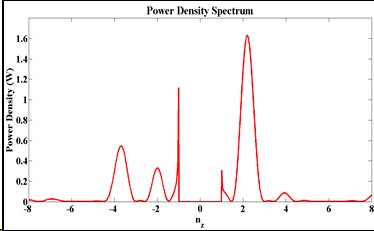
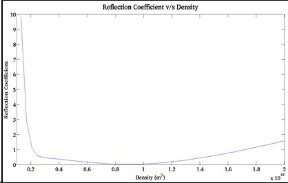
(i) Design and simulation of high power passive-active-multijunction (PAM) launcher
(ii) Design and simulation of high power isolator with matched/short output
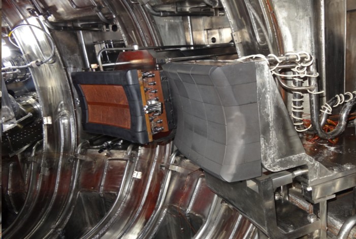
Designed, developed & successfully installed grill antenna in SST1 tokamak for launching lower hybrid slow waves for driving plasma current non-inductively. The figure depicts Integration of grill launcher (UHV/baking compatible) in SST1 tokamak
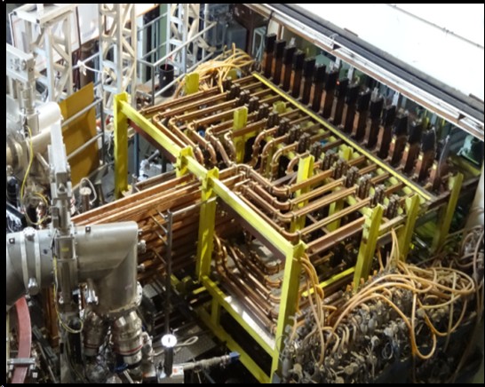
High power CW rf components has been designed, simulated and tested at rated power like WR284 waveguides, E-bend, H-bend, loads, waveguide transformer, etc. and finally integrated in to the complex transmission line network, arranged in four layers as shown in the adjacent figure. Up to ~400 kW rf power launched in to SST1 for ~350ms.
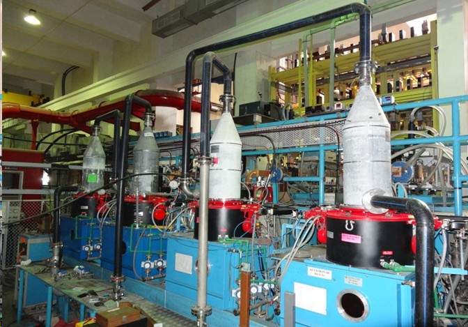
2 MW-CW 3.7GHz., LHCD system has been developed using four klystrons, each rated for 0.5MW-CW rf power. Four high power klystrons are operated with single HVDC PS in parallel configuration. Two klystron tanks (in blue) developed indigenously and tested successfully.
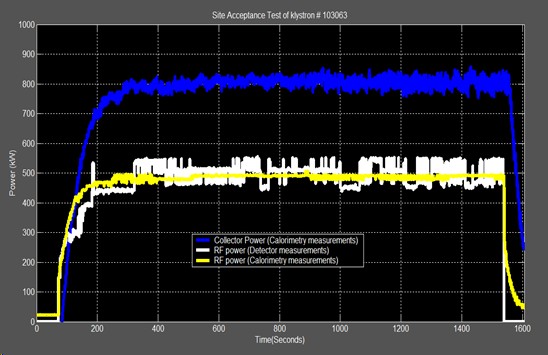
Full power CW operation of klystron demonstrated. 500 kW rf power obtained with DC input power of ~1.2 MW. Blue trace represents dissipation in the collector whereas yellow (white) traces shows output rf power measured with calorimetric technique (schottky diode).
Recent Publications:
“Design and simulation of 3.7 GHz, 8 kW CW and 16 kW magnetrons for LHCD system of tokamaks”
IEEE Trans. on Electron Devices, 69(3), 1461-1467, 2022.
“Current drive experiments in SST1 tokamak with lower hybrid waves”
Nuclear Fusion, 62, 056020, 2022.
“Development and testing of prototype interdigital TWA for fast wave current drive in SST-1 tokamak”
Fusion Engg. and Design, 175, 113000, 2022.
“Design of a 3.7 GHz, TE10 – TE30 mode converter using stepped impedance transformer for CW applications”
Jour. of Electromagnetic Waves and Applications, 35(13), 1699, 2021.
“Design of a 3.7GHz, 1 kW CW hybrid radial power divider for LHCD system of SST1 tokamak”
Fusion Engg. and Design, 173, 112864, 2021.
“Design and simulation of an interdigital travelling wave antenna for fast wave current drive in SST1 tokamak”
Fusion Engg. and Design, 172, 112782, 2021.
“Simulation studies on stacked magnetrons for enhanced power output suitable for power combining applications”
IEEE Trans. on plasma science, 49(2), 680, 2021.
“Computational studies on fast wave current drive in high beta SST1 and SST2 plasmas”
Physics Letter A, 390, 127106, 2021.
“Design of a 3.7GHz, 1 kW CW solid state driver for LHCD system of the SST1 tokamak.”
Fusion Engg. and Design, 158, 111692, 2020.
“Steady state operation of high power CW circulator: Challenges and solutions through simulation and experiments.”
IEEE Transactions on Plasma Science, 48(5), 1290, 2020.
“Multiphysics Analysis of the Passive Active Multijunction (PAM) launcher for LHCD system of ADITYA-Upgrade Tokamak”
Yogesh M. Jain, P. K. Sharma, Harish V. Dixit, Fusion Engg. & Design, 147, 111225, 2019.
“Recent activities on SST1 and ADITYA-U tokamaks".
Plasma and Fusion Research, 13, 3502100, 2018.
“RF design of Passive Active Multijunction (PAM) antenna for LHCD system of ADITYA-U tokamak”
Fusion Engg. & Design, 134, 109-117, 2018.
“Effect of colloidal processing on densification and dielectric properties of Ba(Zn1/3Ta2/3)O3 Ceramics"
Ceramic International, 43 (15), 12658-12666, 2017.
“Design Data for Quick Development of Folded H Plane Tee at High Average Power Level”
Sadhana, Springer, 43(3), March, 2018.
“Design of a 500 kW CW Water Load at 3.7 GHz for the LHCD System of SST-1 Tokamak”
Fusion Engg. & Design, 121, 2017, 32-38.
“Design of the 3.7 GHz, 500 kW CW Circulator for the LHCD System of the SST-1 Tokamak”
Fusion Engg. & Design, 119, 2017, 51-60.
“Overview of recent experimental results from the Aditya tokamak”
Nucl. Fusion, 57, (2017), 102008.
“Initial results in SST1 after upgradation”
Journal of Physics: Conf. Series, 823, (2017), 012004,
- Magnet Technologies
- Fusion Science
- Indigenous Cryo Technology
- Plasma Facing Components Technologies
- Fusion Blanket Technologies
- Beam Technologies
- Large Volume Cryoplant Systems
- Heating & Current Drive Systems